Building a Holiday LED Light Controller with a Microcontroller

Somewhere in the loft there is a box of LED strings, and inside it is the controller that came with them. It offers eight patterns, you use one of them, and the remote control vanished two seasons ago. Replacing that little plastic box with a microcontroller and a few transistors is one of the most satisfying weekend builds in hobby electronics: the wiring is straightforward, the code is short, and the result is visible from across the street.
Start With the Electrical Reality
Most consumer LED strings fall into two camps. The cheap ones run from a low-voltage DC supply — 5 V, 12 V or 24 V — with the LEDs wired in parallel groups, and the control box simply switches the negative side of each colour channel. Addressable strings such as WS2812 types are different: every LED carries its own driver chip, and one data line carries the whole show.
This project is about the first kind, because that is what fills hardware shops in December. The important constraint is current. A single colour channel on a long string can pull one to three amps, and no microcontroller pin will survive that. So the microcontroller makes the decision — when to switch, and for how long — while a MOSFET carries the load. That division of labour is the entire design.
Parts You Actually Need
- A microcontroller board: Arduino Nano, Uno, ESP32, or an ATtiny if you are comfortable with the toolchain. You need at least four PWM-capable pins.
- One logic-level N-channel MOSFET per channel — IRLZ44N, IRL540N and similar. Logic-level is not optional. A regular IRF540 expects around 10 V on the gate and will run hot and dim when driven from a 5 V pin.
- Gate resistors of 100–220 Ω and 10 kΩ pulldown resistors, one of each per channel.
- A DC power supply sized for the strings, plus an inline fuse on the positive feed.
- Perfboard or a screw-terminal breakout, and wire rated for the current you are switching.
- Optional: a push button or rotary encoder for pattern selection, and a real-time clock module if you want the display to switch itself off at a sensible hour.
Wiring, Power and Heat
Add up the strings before you buy a supply. Four channels at 2 A each is 8 A, and a supply running near its rating for five hours a night will not last as long as one with headroom — plan for roughly a third more capacity than you think you need, and fuse the feed.
Wire each channel as a low-side switch: the LED string's positive lead goes to the supply positive, the negative lead goes to the MOSFET drain, the source goes to supply ground, and the gate goes to the microcontroller pin through the gate resistor. The 10 kΩ resistor from gate to ground keeps the channel firmly off while the board boots.
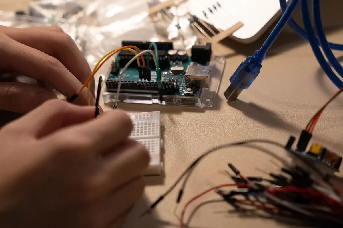
Breadboards are for prototyping only. Above an amp or so, spring contacts warm up and the voltage sags. Solder the MOSFETs to perfboard, use screw terminals for the string wires, and keep the high-current return path short and thick. Connect the microcontroller ground and the LED supply ground at one point near the MOSFET sources; without that common reference the gate signal floats and the outputs behave unpredictably.
Heat is rarely a problem here. A MOSFET in a TO-220 package dissipates roughly I² × RDS(on), so 2 A through 0.03 Ω is about 0.12 W — barely warm. Tiny SMD modules rated optimistically are the ones that cook. One more thing: if you are tempted to switch mains-powered strings instead of a DC supply, use a properly rated relay module or smart plug, and have the mains side checked by a qualified electrician. Everything below assumes low-voltage DC.
PWM and Timers: The Two Ideas That Matter
Pulse-width modulation is just fast switching. If the gate is on for 30 percent of each cycle, the string sees 30 percent of its current on average and looks dimmer. Because the LEDs always run at full forward current rather than a reduced one, the colour stays consistent as you fade — which is why PWM beats analog dimming for lighting.
Frequency matters more than beginners expect. Below about 100 Hz the eye catches flicker when something moves through the beam, and phone cameras show banding even at a few hundred hertz. An Arduino's default 490 Hz is workable indoors; nudging the timer prescaler into the low kilohertz range makes video look clean. An ESP32 is more flexible, since its LEDC peripheral lets you set frequency and resolution independently.
Use hardware PWM wherever the pins support it, and let timers set the rhythm for everything else. The rule that keeps a display smooth is simple: nothing in your sketch should block. A single delay() call freezes the whole program, so one channel's fade stalls the other three. Record the time of the last change and compare it against millis() instead.
Finally, remember that duty cycle is not brightness. Perceived brightness is roughly a power function of the light level, so a linear ramp from 0 to 255 looks like it sits near the top of the range and then falls off a cliff. Square the value or push it through a small lookup table, and the fade finally feels even.
Writing the Control Code
The sketch needs three pieces: a function that writes four channel levels to the PWM pins, a set of pattern functions that compute those levels from elapsed time, and a scheduler that decides which pattern is running. A typical loop looks like this:
levels[] holds four numbers from 0 to 255, one per channel.
setLevels(levels) is the only place the hardware is touched.
Each pass: now = millis(); if now - lastStep >= stepDelay, advance the current pattern by one step, call setLevels(), and set lastStep = now.
A button press changes the pattern index; the patterns themselves live in an array of functions.
Keep step delays in variables rather than baking them into the code. A chase at 120 ms per step is lively; the same chase at 400 ms becomes a slow, calm wave, and one number changes the mood of the whole display. Add a master brightness multiplier that scales every channel before it is written — that gives you a single knob for dimming the entire arrangement when the neighbours start looking out of their windows.
Patterns Worth Programming
- Gentle fade. All channels breathe together between two levels over four to eight seconds. This one benefits most from gamma correction.
- Chase. One channel at a time, wrapping around. Vary the step delay for different speeds.
- Twinkle. Random channels to random levels. Seed the generator from an unconnected analog pin so the sequence differs on every power-up.
- Wave. Drive each channel with a sine function and offset the phase per channel, so the colour appears to travel along the string.
- Flicker. A short random walk around a base level, updated every 30–60 ms, gives a convincing candle effect.
- Schedule. An RTC module or network time lets the controller switch everything off after a set hour and back on at dusk.
Testing, Mounting and Living With It
Build it with one channel first, then one short string, and only then scale up. Run it for twenty minutes indoors and put a hand on the MOSFETs and the supply — both should be warm at most. Watch for a channel that stays slightly lit when it should be off; that usually means a floating gate or a shared ground that is not actually shared.
For the finished version, put the board in a sealed project box with cable glands or grommets, tie the string cables to something solid for strain relief, and leave a drip loop in every lead so water runs off rather than into the enclosure. Keep the box off the ground and the supply indoors. Label the channels with tape before you forget which wire is which in the dark.
The best sign that the build worked is that nobody notices the box behind the bush. They just see the lights doing something better than eight preset patterns.
Photo: kahalb / Pixabay